
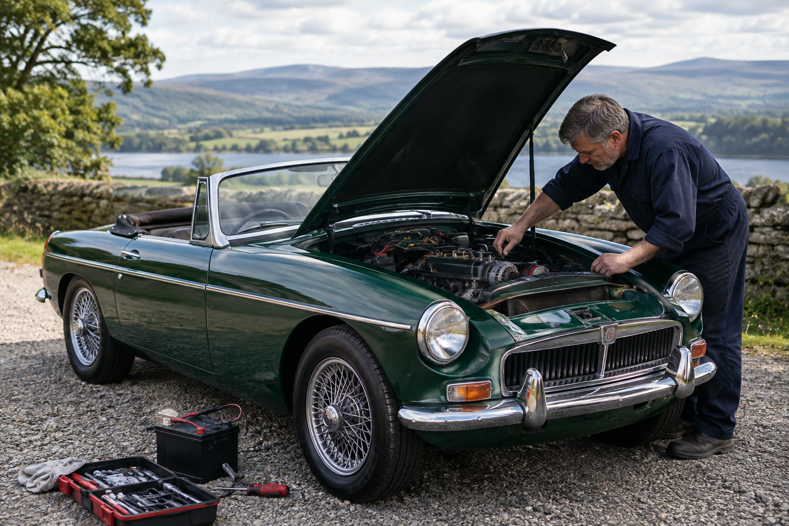
The electrical system in an MGB is relatively straightforward, especially when compared with the systems found in many modern cars. That simplicity is helpful: faults can often be traced with a wiring diagram, a multimeter and a methodical approach. However, an older car may have experienced decades of use, repairs, modifications, moisture and vibration. Electrical problems are therefore not always caused by a single failed component.
A poor earth, loose connection or tired section of wiring can create symptoms that appear to point elsewhere. A dim headlamp may be caused by a switch, a connector, a fuse, the wiring itself or an earth connection. Treating the symptom without finding the underlying cause can lead to repeated failures.
This guide explains the main parts of an MGB electrical system and sets out a sensible way to investigate common problems. It is intended as practical background for owners, rather than a substitute for the correct workshop manual or qualified electrical work.
Start with the battery and its connections
The battery is the foundation of the car's electrical system. Before investigating individual circuits, check that it is securely mounted and that its terminals are clean and tight. Corrosion around a terminal can increase resistance, while a loose connection may cause intermittent faults that are difficult to reproduce.
Inspect the positive and negative cables along their visible length. Look for damaged insulation, hard or swollen sections, fraying and signs of heat. The connections at the battery, starter and body earth points deserve particular attention. A cable can look acceptable externally while being weakened internally, so movement, heat or repeated electrical symptoms should not be ignored.
A battery that has been left discharged for a long period may not recover fully. If the car is difficult to start, do not assume immediately that the starter motor or ignition switch is at fault. Check the battery's condition and charge first, then consider whether the charging system is replenishing it correctly.
Understanding the charging circuit
The charging system is responsible for restoring energy to the battery while the engine is running and supplying current to the car's electrical equipment. Depending on the car's specification and production period, an MGB may be fitted with a dynamo or an alternator. The correct testing procedure and expected readings depend on which system is installed.
Begin with the drive belt. It should be correctly tensioned and in suitable condition. A slipping belt can reduce charging performance and may produce a noticeable squeal, although not every belt problem is obvious. Check the pulley alignment and look for oil contamination or cracking.
Next, inspect the connections at the charging unit, battery and relevant control equipment. A charging warning lamp that behaves unusually can provide a useful clue, but it should not be the only test. If the battery repeatedly becomes flat after the car has been driven, measure the charging voltage using the appropriate procedure for the car's system. Compare the result with reliable technical information for that particular unit rather than relying on a general figure.
Charging problems can arise from a failed regulator, worn brushes, damaged wiring, poor earthing or a defective alternator or dynamo. Replacing the battery without addressing the cause may only postpone the problem.
Why earthing matters
Many apparently complicated MGB electrical faults are caused by inadequate earthing. Electrical current needs a complete path back to the battery. On a classic car, that path may depend on straps, bolts, brackets and painted body panels that have been exposed to moisture and movement over many years.
Important earth points should be clean, tight and free from heavy corrosion. Common areas to inspect include the battery earth connection, the engine-to-body earth strap, lighting earths and connections serving instruments or accessories. When cleaning an earth point, avoid removing more material than necessary. The aim is to create a sound metal-to-metal connection and then protect it appropriately from moisture.
Symptoms of an earthing fault vary. Lamps may glow dimly, an indicator may operate strangely, gauges may behave erratically or a component may work only when the car is being driven over uneven ground. A temporary test lead can sometimes help identify a poor earth, but it should not be treated as a permanent repair unless it is correctly installed and protected.
Using a multimeter safely
A basic digital multimeter is useful for checking voltage, continuity and resistance. Read the instructions for the meter before use, and select the correct function and range. Connecting a meter set to measure current across a power source can cause a short circuit and damage the instrument or wiring.
For a voltage test, connect the probes in parallel with the part of the circuit being checked. A continuity or resistance test should normally be carried out with the circuit switched off and, where appropriate, disconnected from the battery. Do not use a resistance test on a live circuit.
Voltage alone does not always prove that a circuit is healthy. A poor connection may show the expected voltage with no load, yet fail when current is drawn. This is why voltage-drop testing can be valuable. By measuring the voltage across a connection or cable while the circuit is operating, you can identify unwanted resistance that may not be visible during a static inspection.
Fuses, switches and connectors
When an electrical item stops working, establish whether the fault affects one component or an entire circuit. If several items fail together, look first for a shared fuse, feed, switch or earth. If only one item is affected, inspect its local wiring, connector and earth before assuming that the component itself has failed.
Never replace a fuse with one of a higher rating simply to stop it blowing. A fuse is intended to protect the wiring and equipment from excessive current. A repeatedly blown fuse is evidence that the circuit needs investigation. The cause may be a damaged wire, a trapped cable, a failed motor or a component drawing more current than it should.
Connectors can suffer from corrosion, looseness or heat damage. Disconnect them carefully and inspect both sides. A terminal that has pushed back inside a connector may appear connected while making little or no contact. Avoid forcing old plastic connectors, as brittle housings can break and create additional work.
Lighting and indicators
Lighting faults should be approached systematically. Check the bulb, holder, fuse, switch, wiring and earth. If one lamp is dimmer than its equivalent on the other side, compare the two circuits. The comparison can quickly reveal whether the problem is local to the lamp or related to a shared supply.
Headlamp performance can be affected by resistance in the supply or earth connections. Inspect the connectors for signs of heat or discolouration, particularly where a high-current circuit has developed a poor contact. Ensure that replacement bulbs are suitable for the lamp unit and that the bulb is correctly seated.
Indicators and hazard warning lights can be especially informative when diagnosing a fault. If the indicators work but the hazards do not, or vice versa, the relevant switches, feeds and connections should be compared. A rapid flashing rate may indicate a problem with a bulb or the circuit's load, but the exact interpretation depends on the car's configuration.
Instruments and auxiliary equipment
Instruments that stop working together may share a supply or voltage stabilising arrangement. Before removing the dashboard, check the fuse, supply connections and earths. Instruments can also be affected by damaged printed circuit boards, loose terminals or previous work behind the dashboard.
Accessories such as radios, electric fans, alarms and additional gauges may have been installed after the car left the factory. These additions are not necessarily a problem, but poorly routed or inadequately protected wiring can complicate fault-finding. Look for unfused feeds, cables rubbing against metal edges and connections made by twisting wires together or using unsuitable tape.
If an accessory is no longer required, consider whether it should be removed properly rather than simply disconnected. Unused live wires can remain a source of short circuits. Any alteration should be documented so that a future owner or technician can understand what has been changed.
Preventive electrical maintenance
Regular inspection is usually more effective than waiting for a failure. During routine servicing, examine the battery area, earth straps, fuse box, visible harnesses and charging-system connections. Keep water out of connectors and avoid directing high-pressure water at electrical components.
Where a car is being restored or substantially rebuilt, the wiring harness and its routing deserve the same care as the mechanical parts. Wires should be supported, protected from sharp edges and kept away from excessive heat and moving components. Original-looking wiring is not automatically safe, while a carefully installed replacement harness can improve reliability if it is appropriate for the car.
For owners considering a rebuild or detailed specification work, the MGB rebuild specification page provides a useful starting point for discussing the intended approach. If you need advice about a particular car or electrical concern, you can contact California Classics (Hull) Ltd.
A sensible diagnostic sequence
- Confirm the exact symptom and whether it is constant or intermittent.
- Check the battery condition, terminal security and main earth connections.
- Identify the affected circuit using the correct wiring diagram.
- Inspect the fuse, switch, connectors and local earth.
- Test for supply voltage and, where necessary, voltage drop under load.
- Repair the cause, secure the wiring and retest the complete circuit.
A methodical approach saves time and reduces the temptation to replace parts without evidence. It also helps preserve the character of an MGB while improving its dependability. If you are looking for an MGB to own, the current stock page shows the cars presently listed by California Classics (Hull) Ltd, while the sold cars page offers a record of previously listed examples.
Electrical reliability is not about adding unnecessary equipment or disguising every age-related detail. It comes from sound connections, correctly protected wiring, healthy charging components and careful maintenance. With those basics in place, the MGB's relatively simple electrical system can be understood, maintained and repaired without guesswork.